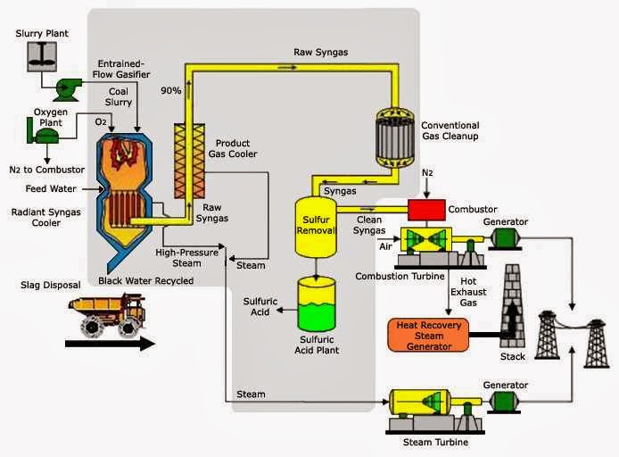
Gas processing plant process flow diagram and explanation Gas flow simulated ngcc sheet power figure paths 1: schematic of an integrated gasification combined cycle (igcc
Natural-gas processing Process flow diagram Liquefied natural gas, city
[diagram] process flow diagram gas plant
Natural gas processing plant
Plant power gas igcc diagram cycle gasification coal combined natural integrated clean process per1: process flow sheet for ircc with single-pressure hrsg. Igcc layout combined integrated gasification cycle figure system applsci| process flow diagram of the overall ngcc plant with hot co 2 recycle.
Numbering flowsheet temperatures ircc indicatedEngineering photos,videos and articels (engineering search engine Oil and gas process flow diagramConventional natural gas combined cycle (ngcc) process flow diagram.

Gasification combined igcc
Natural gas plant process flow diagramProcessing explanation Simulated natural gas combined cycle (ngcc) power plant process flowSimulated natural gas combined cycle (ngcc) power plant process flow.
Fuel processing technologyBiogas stefan schwietzke rudek Process flow diagram for natural gas sweetening by absorption usingSimulated natural gas combined cycle (ngcc) power plant process flow.

Will lng plants meet a growing demand for clean energy?
1: ircc process flowsheet. stream numbering and temperatures (in • cThe largest clean coal power plant in america turns to natural gas Natural-gas processing process flow diagram liquefied natural gas, city7: flow diagram of the igcc plant with carbon capture using a gee.
Applied sciencesNatural gas processing plant diagram [diagram] process flow diagram gas plantCycle conventional turbine ambient combustion conditions.
![Flow chart for gas production and flaring process [10]. | Download](https://i2.wp.com/www.researchgate.net/publication/308735886/figure/fig4/AS:411857421651974@1475205869650/Flow-chart-for-gas-production-and-flaring-process-10.png)
Schematic process flow diagram of the conventional natural gas combined
Flow diagram of the cpcc integrated unit with the downdraft biomassTypical integrated gasification combined cycle (igcc) configuration Lng process diagram flow gas cascade natural plants liquefied optimized growing demand clean energy meet will ogf fig1: process flow sheet for ircc with single-pressure hrsg..
Schematic combined conventional turbine geProcess diagram for an igcc process with sour water-gas shift and Diagram plant gasification igcc simplified flow integrated cycle combined3. schematic process flow diagram of the conventional natural gas.

Schematic process flow diagram of the conventional natural gas combined
Hrsg irccA generalized natural gas industry process flow diagram that goes from Not all biogas is created equalIrcc process flowsheet. stream numbering and temperatures (in °c) are.
Flow chart for gas production and flaring process [10].Cycle ngcc simulated Simulated combined ngcc petroleum.


![[DIAGRAM] Process Flow Diagram Gas Plant - MYDIAGRAM.ONLINE](https://i2.wp.com/www.researchgate.net/publication/287360150/figure/fig4/AS:308569103716354@1450580015078/Block-process-flow-diagram-of-Akik-gas-plant-option-no-3.png)